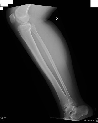
LATERAL LEG PROJECTION
Lateral • Mediolateral view • Sagittal evaluation of tibia and fibula
Exposure Factors
Equipment: Without bucky. Position: Lateral decubitus.
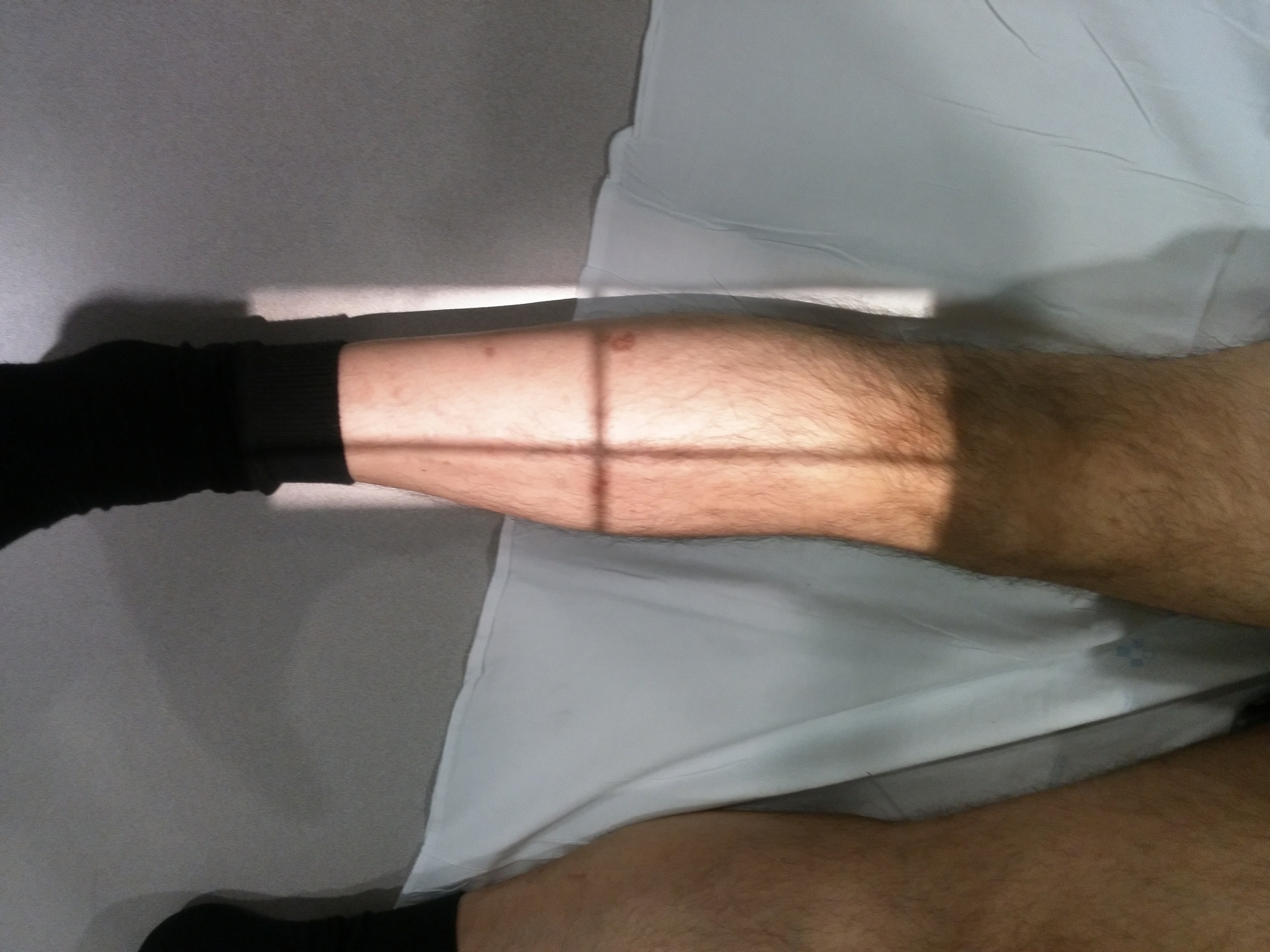
TRUE LATERAL POSITION
The affected extremity must be completely in lateral position
Plate Size
Visible Anatomical Structures
Tibia
Complete lateral view
Fibula
Complete lateral view
Malleoli
Lateral visualization
Joints
Knee and ankle
- Complete tibia - Diaphysis in sagittal view
- Complete fibula - Diaphysis in sagittal view
- Malleoli - Distal processes in lateral view
- Trochlea of talus - Articular surface of talus
- Knee joint - Femorotibial in lateral view (if included)
- Ankle joint - Tibiofibular-talar in lateral view (if included)
- Tibial and fibular diaphysis - Bone bodies in profile
- Tibia-fibula relationship - Interosseous space in lateral view
- Articular cartilage - Joint spaces in profile
Patient Positioning
CRITICAL ALIGNMENT
Chassis axis = Leg axis
Precise alignment between longitudinal axis of chassis and longitudinal axis of leg for optimal visualization
Central Ray Direction
Exactly at center of leg and vertically
Entry point: Medial, midline of leg
Exit point: Lateral, midline of leg
Centered: Midpoint between knee and ankle
Target: True lateral visualization of bone structures
Patient Instructions
"Remain still during the examination"
Maintain exact lateral position - Do not move leg during exposure
Technical Considerations
Critical Alignment
Precise alignment between chassis axis and leg axis for true lateral view.
Contralateral Position
Healthy extremity flexed and supported for maximum stability.
Complete Inclusion
Ensure visualization of entire tibial and fibular diaphysis.
Clinical Indications
Image Quality Criteria
True Lateral View
Tibia and fibula visualized in profile without rotation
Perfect Alignment
Chassis axis perfectly aligned with leg axis
Complete Inclusion
Complete diaphysis of both bones included
Complete Radiological Study
COMPLEMENTARY PROJECTIONS
The lateral leg projection is typically performed together with:
These two projections provide three-dimensional evaluation of bone structures
Adaptation to Patient Size
Chassis size is adapted according to patient characteristics:
This adaptation ensures complete inclusion of all anatomical structures